April 2011
Due to the need of understanding the sequences of events at all failed units, PCTRAN was used within the first week following the event. Preliminary result was first posted on Micro-Simulation Technology’s website on March 21, 2011. It has basically reproduced core degradation, operator induced containment depressurization followed by hydrogen explosion in the reactor building sequences at three of the four units. The other non-operating Unit 4 also resulted in over-heating of the spent fuels and hydrogen explosion. We have done its simulation by using our simulator SFP.
The earthquake caused instant loss of offsite power. The scale-9 shock far exceeds plant design limit of scale 8.2. Onsite emergency diesel generators started to provide AC power for residual heat removal. But soon they were knocked out by the tsunami. There was limited DC battery power for valve control, etc. A complete station blackout (SBO) then followed without any means for coolant makeup and heat removal..
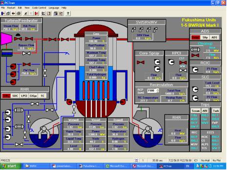
Fukushima Daiichi Unit 1 is a GE BWR-3 rated 460/1380 MW (electric/thermal). Units 2 to 5 are BWR4 rated at 784/2381 MW. There are two external recirculation pumps. Jet pumps inside the reactor downcomer enhance the core flow for better efficiency. They all have Mark I (steel liner plus concrete drywell and torus-shaped suppression pool) containments. The emergency core cooling systems contain a steam-driven High Pressure Coolant Injection (HPCI) system. It starts on low reactor water level signal and draws water initially from the condensate storage tank. There is another Reactor Core Isolation Cooling system also powered by the reactor steam. It starts on main steam isolation and low reactor water level signal. A small constant flow provides coolant makeup until its battery control runs out of power. On the active side, the diesel generator-powered residual heat removal (RHR) pumps turn on low reactor water level. to inject water in the Low-Pressure Coolant Injection (LPCI) mode. It provides large flow to reflood the core after the reactor pressure is lowed by either a pipe break or forced depressruization. Figure 1 is the PCTRAN mimic during full-power steady state operation.

Unit 6 of Daiichi and all four units in the neighborhood Daini site are BWR5 rated at 1110/3293 MW. Mark II containment has its suppression pool connected by vertical vent pipes underneath the drywell. The emergency core cooling system is different by using high-pressure core spray (HPCS) system instead of HPCI. Spray gets more uniform droplet distribution on top of the fuels than injection from the bottom.
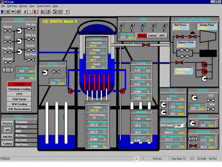
Fig. 2 PCTRAN BWR5 Mark II Mimic
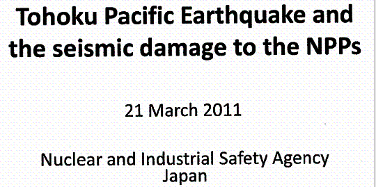
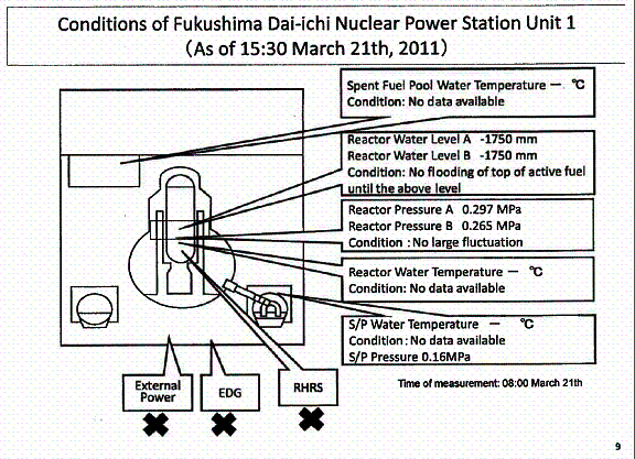
The following report provided by Mr. Seong-Deuk Jo of International Atomic Energy Agency was used in our study:
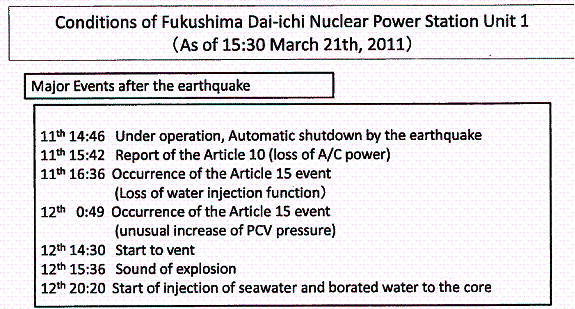
Time |
Seconds from earthquake |
Event reported |
Event conduct on PCTRN simulation |
11th 14:46 |
0 |
Reactor automatic shutdown |
Reactor Manual scram, trip both recirculation pumps, all MFW pumps, |
|
> 600 |
Tsunami hit plant loss of diesel |
Isolate turbine bypass valve on loss of condenser vacuum, RCIC starts on Rx water level < L2 |
11th 15:42 |
3,360 |
Report loss of AC, loss of AC article 10 event |
|
11th 16:36 |
6,600 |
Loss of water injection Article 15 event |
Stop RCIC |
11th 18:46 |
14,400 |
End of Part 1 |
End of Part 1 = Beginning of Part 2 |
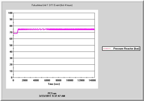
Reactor pressure vessel pressure - pressure cycled around 1st SRV set point of 75 bar
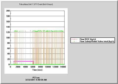
RCIC flow and SRV discharge flow – RCIC was lost around 6,000 sec by the tsunami
damage or running out of DC battery. Article 15 event declared.
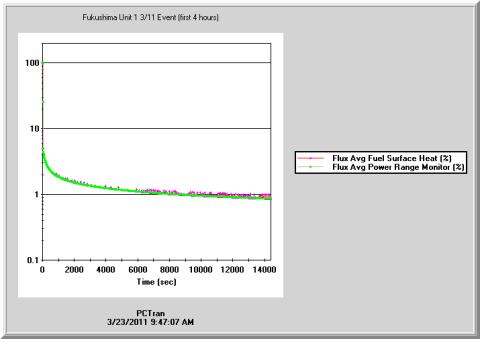
Core decay heat.
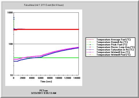
Fuel and reactor coolant temperatures stable after reactor trip; suppression pool and air temperatures heated up by SRV steam discharge; drywell air temperature increased slightly by flipping of the vacuum breaker between drywell and wetwell.
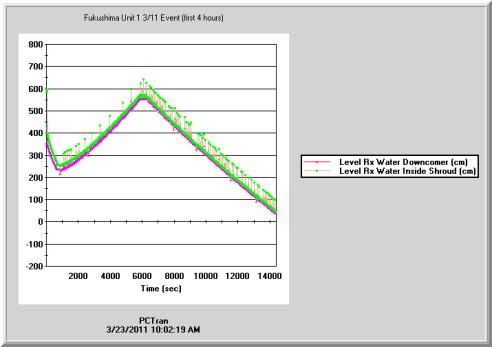
Reactor water level above top of active fuel – RCIC started at 600 sec to makeup SRV loss; terminated around 6600 seconds so the level dropped.
Nothing about the extent of core damage from the later part of Day 1 (March 11) till the 2nd day none was known. The operators noticed the Containment Pressure Vessel (CPV) pressure was unbearably high to face failure. They decided to depressurize the CPV. Soon a sound of hydrogen explosion from the Reactor Building was heard.
The extent of core damage from the later part of Day 1 (March 11) till the 2nd day none was unknown. The operators noticed the Containment Pressure Vessel (CPV) pressure was unbearably high to face failure. They decided to depressurize the CPV. Soon a sound of hydrogen explosion from the Reactor Building was heard.
Time |
Seconds from earthquake |
Event reported |
Event conduct on PCTRN simulation |
12th 0:49 |
36,180 |
Increase of PCV pressure Article 15 event |
After the fuel shows signs of exposure and failure, |
12th |
85,440 |
Start to vent (from PCV to reactor building) |
Operators open one set of SRVs at about 21,000 seconds to depressurize the PCV. |
|
|
|
Operators vent the PCV at about 22,000 seconds to depressurize. |
12th |
89,400 |
Sound of explosion |
Hydrogen concentration in Rx Bldg > 4%, explosion assumed around 28,000 seconds |
12th |
106,440 |
Start injecting sea water to core |
Start injecting water use the HPCI line to reflood the core. |
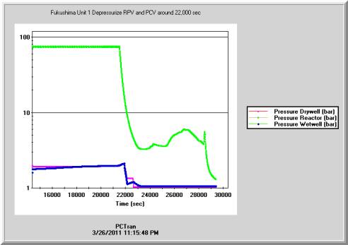
Operator depressurize the RPV and PCV to vent hydrogen
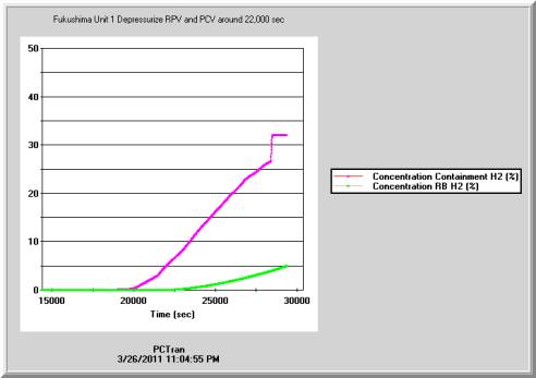
Hydrogen in the Reactor Building reached detonation point (5%) and exploded.
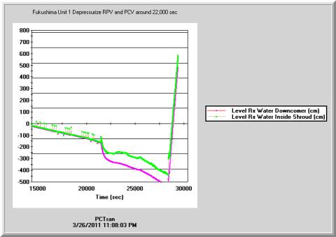
Water level (above top of active fuel) in the RPV; sea water and borated water was
used to recover the core.
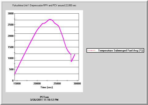
Submerged average fuel temperature
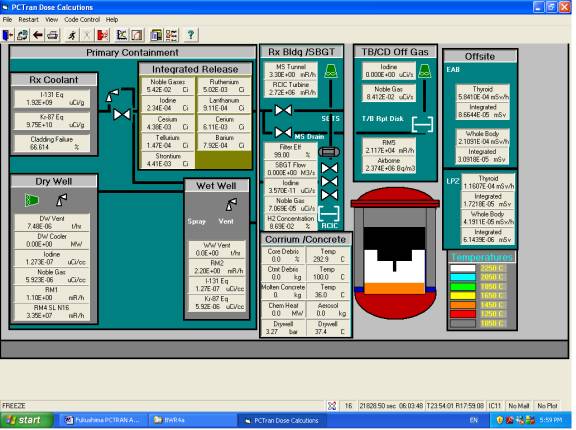
An immediate question is whether a PWR is more resilient to an earthquake/blackout than a BWR. By using our PCTRAN PWR models it is quantitatively analyzed in great details. We may conclude an affirmative “yes” - but not by much - just buy you a few more hours to resume onsite power supply. After that the consequence is the same.
PWR has its own steam generator secondary water inventory. It provides a heat sink for the core decay heat from about 30 minutes to a couple hours. PWR containment is in average four times larger than a BWR’s; so that after emergency depressurization of the primary coolant system, the containment is less likely to elevate to its breach level.
This does not mean all PWR’s are safe enough and nothing should be further examined. Close review and inspection of all passive and active emergency systems are still necessary.
Another significant event is loss of cooling/coolant at Fukushima Unit 4’s spent fuel pool that has caused clad oxidation and radiological release. Micro-Simulation has another simulation product “SFP”. Since 2004 we have advocated that spent fuel pool safety was overlooked and an independent hardened cooling system is necessary. Unfortunately what happened at Fukushima Unit 4 on March 18 has proven our points.
Shown below is SFP software’s main mimic during normal operation. The pool is filled with freshly unloaded and previous cycles’ discharged fuels. Their combined decay heat is removed by the cooling systems.
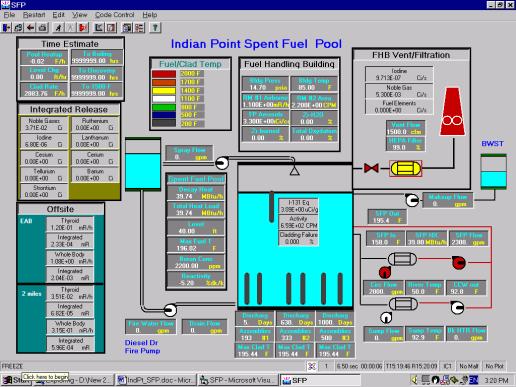
Spent Fuel Pool Simulator – normal condition.
Upon a loss of cooling or coolant event, the pool will heat up to boiling. Continued boiling exposes top of the fuels. Heat-up of the exposed fuel may turn into cladding oxidation and radiological gas release. The scale of a pool’s radiological inventory could be even more serious than a plant’s, since a pool contains much more assemblies than a core.
Since cracks can be developed at bottom of a pool – especially for Mark I and II containment the pool is located high above ground. A supplemental system should be a spray from atop of the pool with its own water storage and lines to outside makeup. Its piping and power supply should be independent and hardened to assure effectiveness in adversity. Having this you would never need helicopters or fire engines.
So, one of the lessons learned from Fukushima spent fuel pool release is:
Every nuclear power plant in the world (both PWR and BWR) should add a hardened spray cooling system.
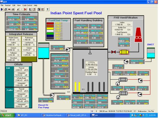
Spent Fuel Pool accident – after loss of coolant or cooling water boiled off. Note, a supplement
pool spray system on top of the pool could keep the fuels cooled to present radiological elease.
Iodine and noble gases release source term is used by another MST product RadPuff for dose dispersion. Mostly southeast wind prevailed in the next couple days, so the plume was projected into the northwest direction.
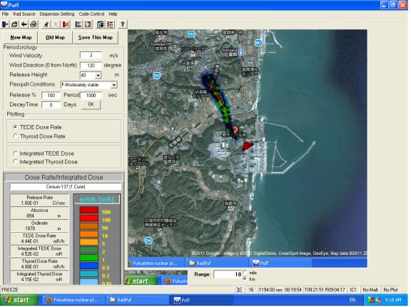
RadPuff projection of dose dispersion following radiological release from the Fukushima site, southeast wind was assumed.
The Fukushima event was unprecedented because it exceeded historical maximum in the region. The succeeding tsunami aggregated the damage that knocked out crucial cooling systems and disabled all diesel generators. Given the initiating conditions PCTRAN is able to reproduce the plant behavior and radiological consequence. Our specific observation/recommendations are:
1. All existing power plants' passive emergency cooling systems (BWR's RCIC and PWR's turbine-driven auxiliary feedwater system) should be inspected and reinforced to assure their reliability during adverse condition. Onsite emergency generators should be further protected.
2. PWR is more resilient than BWR because of its steam generator secondary water inventory and size of containment. This gives larger margin to core damage and containment failure. Further review is still necessary to improve the safety level.
3. Spent fuel pool safety has been grossly overlooked. A hardened and independent top spray system is necessary for all nuclear power plants.