 Home | Contact us
The General Electric Economic Simplified BWR (ESBWR) relies on the use of natural circulation and passive safety features to enhance the plant performance and simplify the design. It was based on the earlier Simplified BWR (SBWR) by economics of scale to a higher power level of 4500 MWt (1560 Mwe). The use of recirculation pumps in previous BWR models or reactor internal pumps for ABWR is completely eliminated. Core flow is by natural circulation.
Normal operation is by the control rod drive system. Since there is no circulation pump for the core flow control, the flux-flow map is a simple natural circulation curve. Setting the header pressure set point in the upper right panel provides turbine header pressure control. The reactor coolant Cleanup system and Shutdown Cooling system are provided in the lower right panel. Operators should control the turbine bypass valves to lower the reactor pressure below the low-pressure RHR pumps’ shutoff head. After that the Shutdown Cooling System can be turned on for cool down to cold shutdown. The cooldown rate must be controlled within a Technical Specification’s rate limit.
Natural circulation is further used for emergency core cooling and containment cooling. In the event of steam line leak or break, the reactor is shutdown by inserting all control rods from the bottom. The feedwater continues to maintain the water level in the vessel.
The core and containment cooling systems are completely "passive", i.e. without using AC-driven pumps and controls. It is demonstrated in GE's website by clicking the "ESBWR Passive Safety Systems Animation" link. Our PCTRAN/ESBWR is the first simulator in the world that has reproduced the video's animation with high fidelity. Not only the loss-of-coolant-accident (in this case a steam line break) in the video was quantitatively reproduced, but also every category in the vendor's design documentation could be benchmarked to reach reasonable agreement. You may download the attached demo version and verify it yourself. Download the free demo.
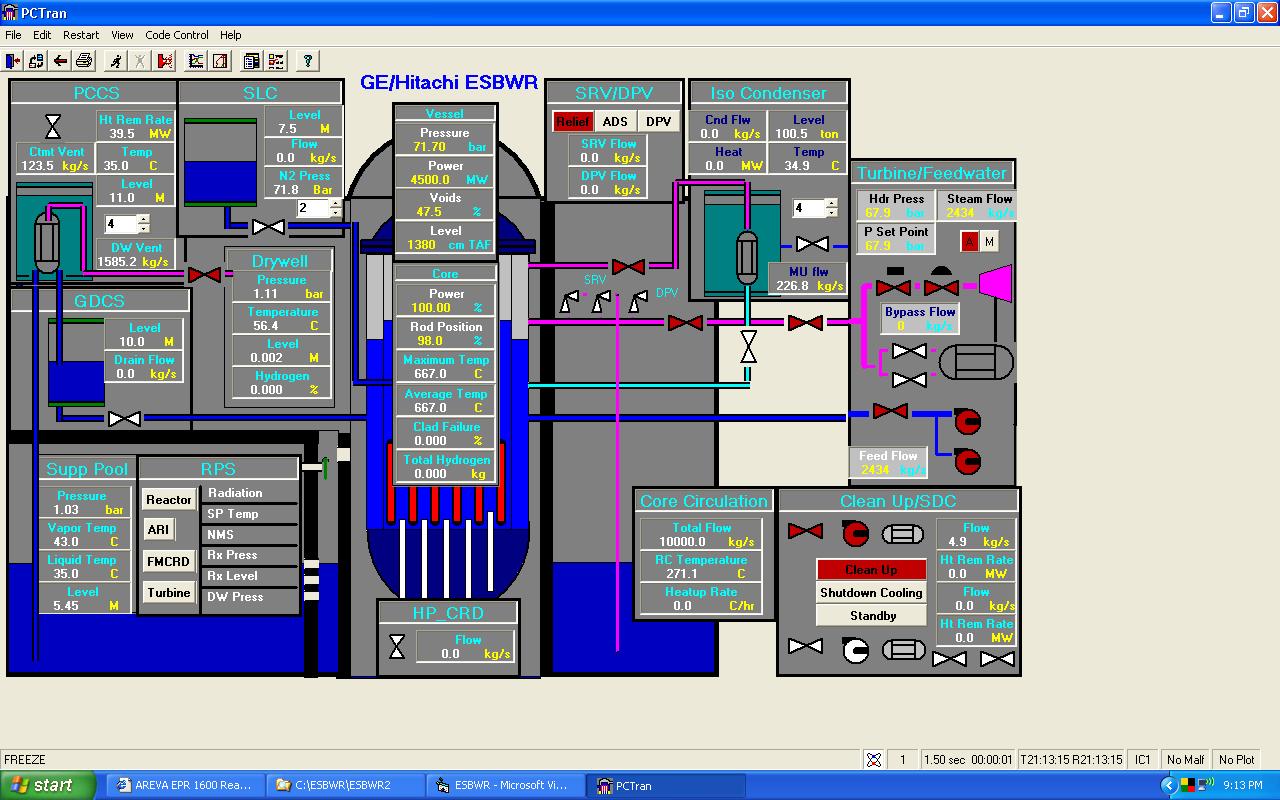
In the event of AC power is lost, the ESBWR utilizes the Isolation Condenser System for high-pressure inventory control and decay heat removal. In PCTRAN/ESBWR main mimic it is located in the upper right of the reactor vessel. Low water Level 2 activates the isolation condenser system. It has four independent loops. By clicking the scroll bar users can activate one to four trains. The steam is driven by natural circulation upward to the condenser tubes; where it is condensed by the pool water and drain back into the vessel.
If the water level continues to fall for a larger break to Level 1, the Automatic Depressurization System (ADS) is activated to allow low-pressure inventory control. The ADS consists of 10 safety relief valves (SRVs) and 8 depressurization valves (DPVs) connected to the steam line. The SRVs discharge steam to the suppression pool and the DPVs discharge to the drywell respectively. A timely sequence of opening of these valves allows the water from the Gravity Driven Cooling System (GDCS) tanks to flow into the vessel by gravity. The Standby Liquid Control system (SLC) is also activated. Again, by clicking the scroll bar users can activate one to two trains. It uses nitrogen-filled tanks to drive borated water for coolant makeup.
Containment cooling is provided by the Passive Containment Cooling System (PCCS) in the mimic’s upper left side. The system contains four loops; each has a heat exchanger open to the containment, a condensate drain line and a vent discharge line submerged in the suppression pool. The PCCS limits containment pressure to 40 psig (about 3.6 atmospheres). The passive systems have been successfully analyzed to maintain the fuel covered at all time (without heat-up) and the containment stay cooled for three days. PCTRAN/ESBWR has duplicated all these scenarios consistent GE/Hitachi Design Control Document Tier 2 26A6642AT, Chapter 6 ECCS and BP Chapter 15 Safety Analysis, Rev. 4 (2007).
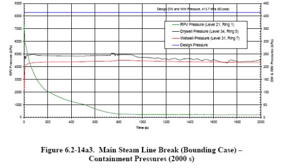
A turbine trip with bypass transient (TTWB) and a main steam line break (MSLB) inside containment bounding case were analyzed using PCTRAN/ESBWR for benchmark against the Design Document2. For TTWB, the Alternate Rod Insertion (ARI) is initiated that reduces the reactor power under 60% with feedwater and steam bypass flow runback to about 45%. Loss of feedwater heating (and thus a greater enthalpy difference to that of steam) is the cause for more reduction in feed and steam flows than the power. The reactor dome pressure, drywell and suppression pool pressures and temperatures are compared in the following figures. They are generally in good agreement.
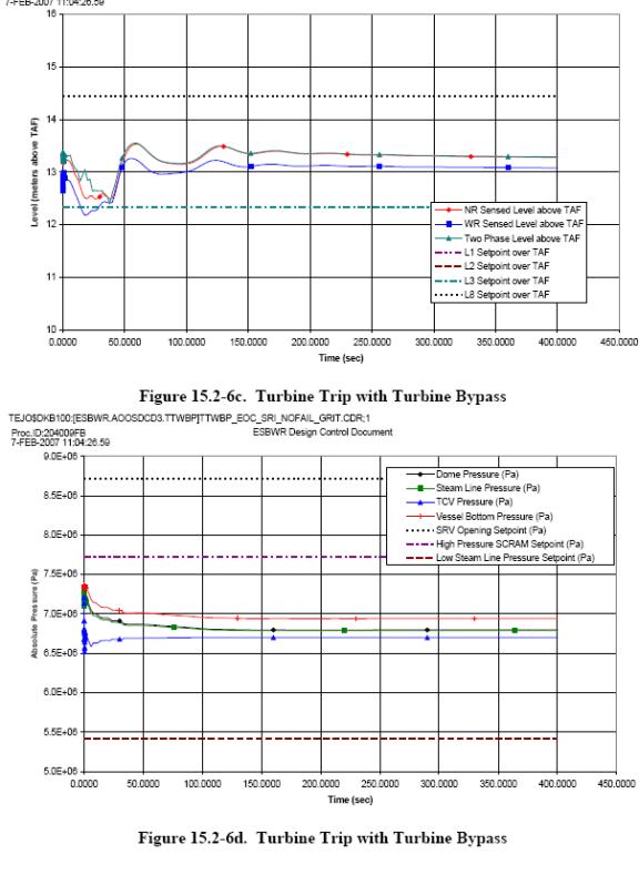
By setting the rod demand to 94% (from original 98%) in 100 seconds, PCTRAN produced power reduction to about 67% and both the feedwater and steam flows dropped to about 42%. The dome and turbine header pressure and vessel downcomer level are all consistent with the Design Document.
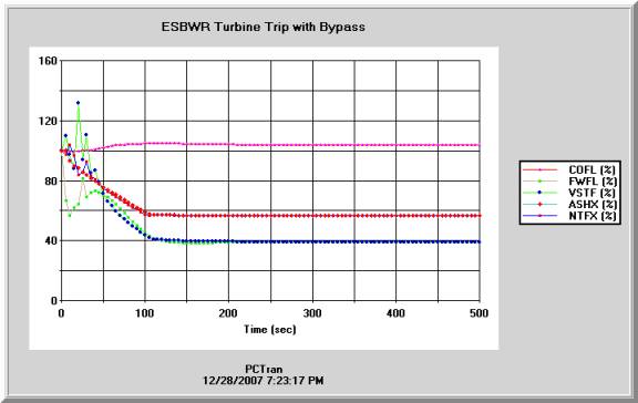
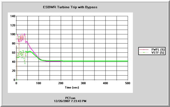
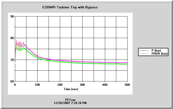
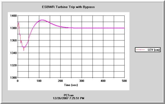
PCTRAN Variables legend LEV = Downcomer water level (TAF), P = Reactor dome pressure, PHDR = Turbine header pressure, FWFL = Feedwater flow, VSTF = Vessel steam flow, COFL = Core flow, ASHF = Average surface heat flux, NTFX = Neutron flux
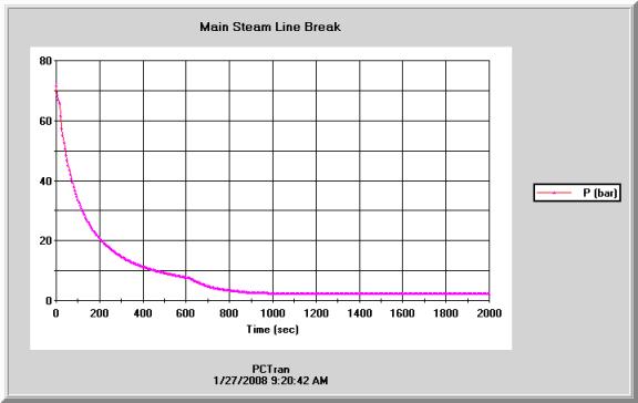
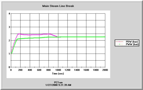
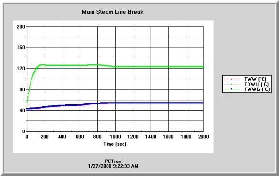
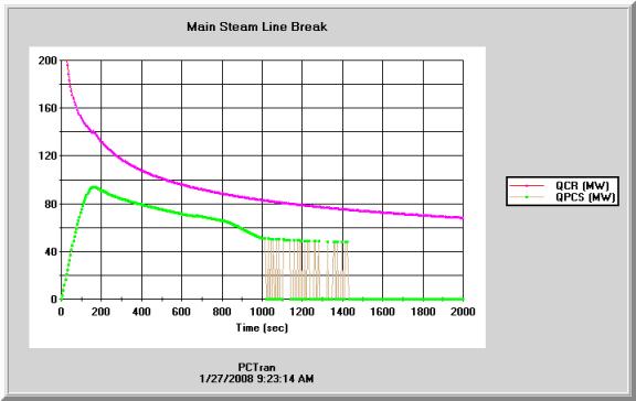
Next a double-ended 950-cm2 steam line break is initiated inside the dry well. The reactor is depressurized while blowdown of the steam inters the suppression pool. Heat-up in the drywell air then enters into the PCCS pool by natural circulation that limits the containment pressure to about 2.4 atmospheres. The PCTRAN/ESBWR results are in good agreement with the Design Document.