 Home | Contact us
Can PC-based Simulator do Full-Course Stratup and Shutdown?
Introduction
Since its early development of PCTRAN, we have focused more on abnormal transients and accidents than normal operation. The motivation was that at the aftermath of the TMI accident, the operators and industry as a whole had shown weakness in handling complex and multiple failures. PCTRAN does have sophisticated control systems for rods, primary and secondary pressure and level controls. Without that the plant cannot be operated properly.
Startup from cold condition all the way up to full power is essential in every operator’s training. At the end of a cycle, power is reduced and nuclear operation is brought down. The plant is further cooled to cold condition. Just like training airplane pilots, no matter how skillful you teach them to handle stormy and turbulent midair condition, they must be able to take the plane up and down safely. This looks simple and naive enough to say the least, but nevertheless if you ask any serious reactor analysts who have experience in running the “state-of-art” codes such as RELAP5 or RETRAN. They will tell you it is next-to-impossibly complicated. Therefore making no excuses for the PC-based simulator, here we demonstrate a “plain and simple” startup and shutdown operation.
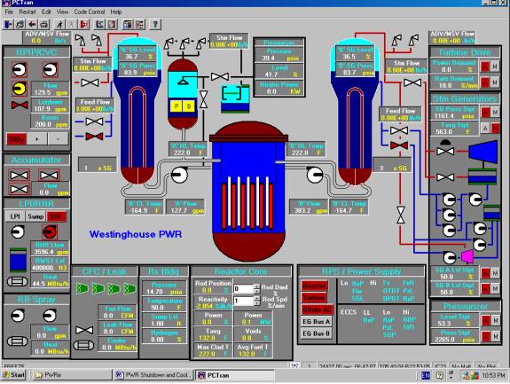
Shown below is the PWR NSSS Mimic. Reactor control is by pulling and inserting the rods in the lower middle “Reactor Core” panel by clicking the “Rod Dmd” and “Rod Spd” blanks. Similarly turbine control is by going to the upper right “Turbine Drive” panel. Other controls such as the pressurizer and steam generator, RC pumps and RHR system are described in the PCTRAN manual.
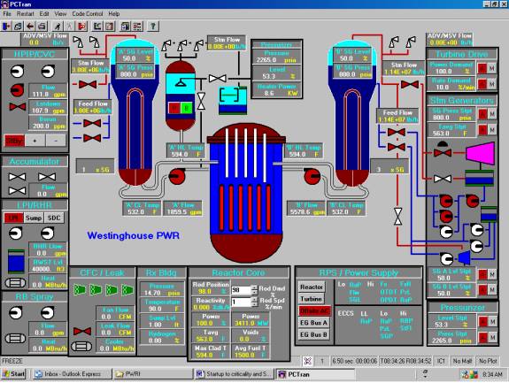
PCTRAN PWR 4-loop NSSS Mimic (in British unit convention: pressure in psia, liquid flows are in gpm, feedwater and steam flows and PORV and safety valve flows are in lb/h according to normal control room convention in the US)
Part 1 Start up
1. Running Reactor Coolant Pumps to heat up the RCS
For a PWR system the coolant is originally cold at room temperature with nitrogen filled inside the pressurizer above the liquid level. Heating up of the RCS is by running the reactor coolant pumps. Then a steam bubble is drawn in the pressurizer to bleed off the nitrogen. Following steps should be conducted:
- Select the initial condition (IC) near cold shutdown condition Tavg = 132ºF, RC pressure = 38 psia.
- Shut off the running RHR pumps.
- Turn on RCP’s to heat up the RCS. The RCP has heat input about 4 MW per pump or 16 MW total for the 4-loop PWR.
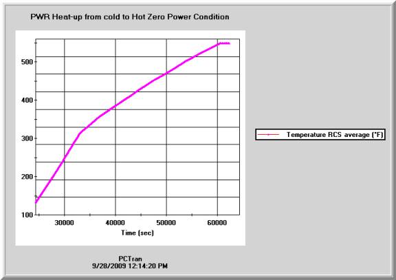
- Since there is over 10,000 ft3 RCS coolant, it takes over 10 hours to heat up to the reactor operating temperature. Click the speed number in the lower status bar to the maximum speed of 16 times faster than real-time.
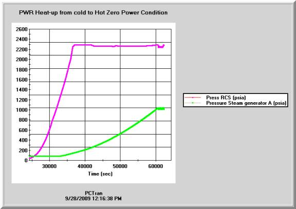
- Turn on the pressurizer heaters to pressurize the RCS. Adjust the heater strength to control the pressurization rate. Switch to auto control when pressure reaches 2250 psia - the operating pressure.
- Throttle the charging pump to maintain pressurizer level around 50%.
- It takes over 10 hours for RC Tavg to reach 548º F – the hot zero power (HZP) temperature. You are ready to conduct the 2nd stage of startup - deboration and pulling the rods to nuclear criticality. Save an IC for future us.
- Deboration and Pulling Control Rods to Criticality
- From the previously saved IC for HZP, we are ready to dilute the RCS boron concentration to offset the Xe and Sm poisoning after previous shutdown. Depending upon whether the time-of-life of the core (beginning, middle or end of cycle), the core boron concentration may range from a few hundreds to over one thousand ppm. Press the “-“ sign in the HPIP/CVC (High Pressure Injection Pump and Chemical and Volume Control) panel, you will witness the boron concentration goes down and total reactivity of the core becomes less negative.
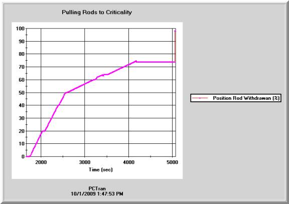
- Next we should pull the rods (assemblies for PWR). In the core panel there are “Rod Dmd” spin value for demand in % and “Rod Spd” for speed in % per minute. Scroll or type in proper values. A specific PWR plant operating procedure should specify the exact values and steps precisely. Here we can pull relatively fast in the early stage (< 60% withdrawn at speed > 1%/min) and use the minimum speed (1%/min) when criticality is approaching (dk/k = 0).
- Around criticality there should be small amount of power shown in the panel. Then wait it to stabilize and save an IC.
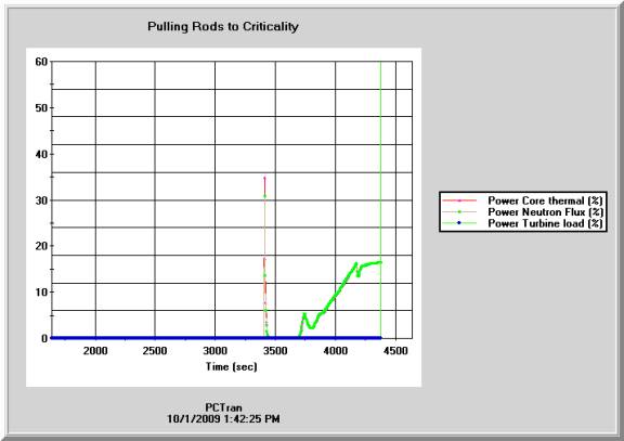
- Continue pulling the rods 1% a time and watch power increase. The initial power surge was caused by pulling the rods too fast and should have been avoided.
- When the power starts to decrease we should pull the rods another percent and go on till the power is > 13%.
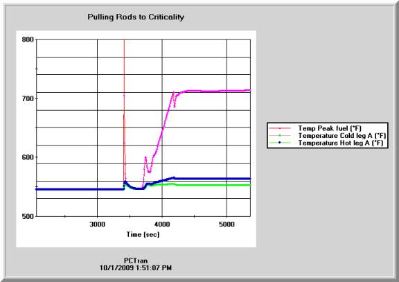
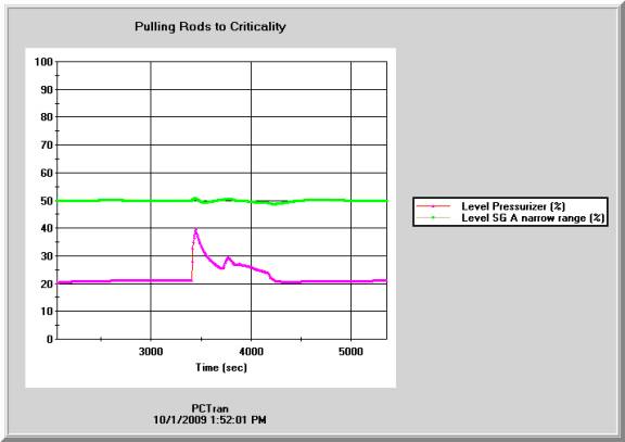
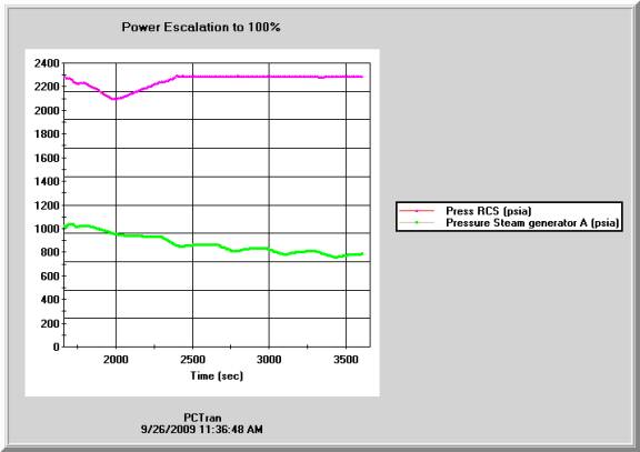
- Save an IC and mark it “Ready for turbine/generator Synchronize”. Shown below are the transient plots. The primary pressures and level are controlled by the pressurizer and CVCS system respectively. Feedwater and steam flows are controlled by the FW control and turbine bypass systems to maintain the SG pressure and level within reasonable ranges.


3. Synchronize Turbine Generator and Power Escalation to 100%
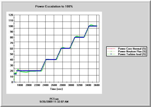
- At power about 15% and stable, we are ready to synchronize the turbine/generator. Simply click on the “Turbine” button in the lower middle “RPS/Power Supply” panel to open the stop valve, the turbine generator will be online. A more sophisticated simulator will model the turbine shaft speed, torque and generator’s electrical voltage, phase and current. “Synchronize” means matching the generator’s current’s phase with the outside grid. Here we consolidate all these by simply redirect the steam flow to the turbine main control valve and shut the bypass valve.
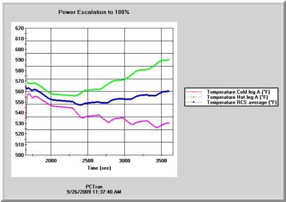
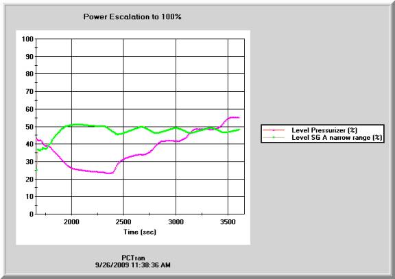
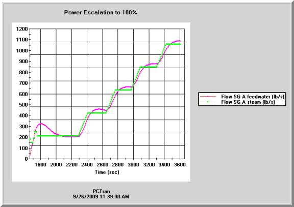
- Next, we shall use the “Turbine Drive” panel’s power demand auto/manual button “A/M” to raise the power demand to 20%, 40%, 60%, 80% and finally to full power. The ramp rate is defaulted to 20% per minutes. In actual plant startup there is a long “hold” period to conduct numerous tests before each power escalation. Following transient plots shows power, pressure, temperature, level and flow rates of both the primary and secondary sides. They follow a typical PWR plant design closely.
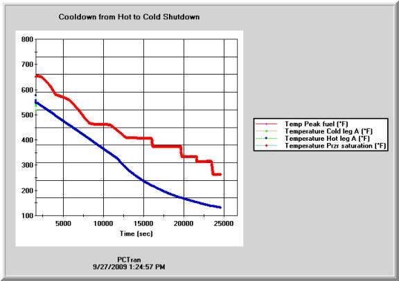
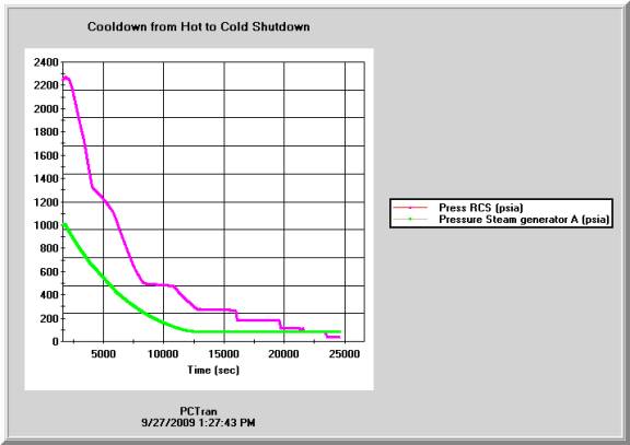
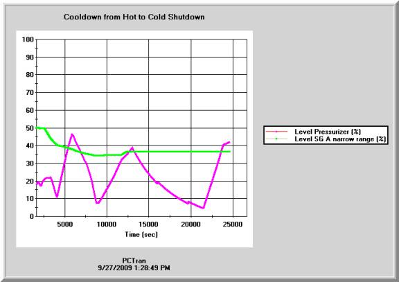
Part 2 Shutdown (including Cooldown to Cold Condition)
Power reduction is similar to ascension by simply typing in a lower power demand one step a time. When turbine power is below 20%, all rods can be inserted or by using the Scram function. After scram the reactor and stabilize at hot shutdown condition for a few hours, operators could start cool-down using the TBV. PCTRAN provides a constant cool-down rate control function. Click the “A/M” button in the turbine control panel and type in the cool-down rate. It must be lower than the Tech Spec limit of 100ºF/hr. During its course, operator shall conduct the following:
- Bypass MSIV closure on low SG pressure by locking open both MSIV’s
- Bypass ESFAS HPSI initiation by disabling the 2 HPI pumps (disabling the top 2 HPI pumps; leave the 3rd charging pump running).
- Disable the pressurizer proportional and backup heaters (malfunction fraction = 0).
- Throttle the pressurizer spray to lower the RC pressure (set valve opening = 2% -10%).
- Throttle the charging pump capacity (20% - 100%) to maintain the pressurizer level 20% - 40%.
- Bypass Accumulator (locking close all 3 accumulator valves).
When the RHR start condition (RC pressure < 400 psig and Tavg < 350ºF ) is met, operators should switch to RHR cooldown by:
- Close all MSIV’s.
- Trip all feedwater pumps.
- Trip all RCP’s at and start one RHR pump in the Shutdown Cooling mode.
- Start and throttle the auxiliary pressurizer pressure to control the RC pressure (normal spray is no longer available after trip of all RCP’s)
- Watch the RT/NDT pressure/temperature limit for thermal shock prevention.
- Cold shutdown is defined as RCS < 120ºF and depressurized.
Following NSSS mimic shows the reactor is near the cold shutdown condition (P = 32 psia and Tavg = 132ºF).