Selection of Base Software
Instead of development from scratch, extensive search in the
industry has been conducted and a number of vendors have been
contacted over the past two years. Evaluating according to the
above areas, a PC-based transient analysis code, PCTRAN[2], developed in the U.S.A, was
selected. Based upon a thermal-hydraulics model using a reduced
set of fluid nodes (compared to full scope simulators) and graphical
man-machine interface, various models have been installed at
a wide range of plants.[3]
The software was further modified considerably during the past
year to meet all the IAEA
set criteria. The product software's constituent models are described
below:
ARS uses a point-kinetics model with one delayed neutron group.
Reactivity changes due to control rod movement and boron concentration
changes as well as feedback from voids, moderator temperature
and fuel temperature (Doppler) coefficients are simulated. The
significant of the feedback coefficients are reactor type and
design specific. After reactor shutdown, a decay heat table provides
the heat input.
The basic thermal hydraulics of ARS are first principle in
mass and energy balance, ensuring credible and realistic simulations.
A non-equilibrium pressurizer model is used for a PWR. A drift
flux model is used for calculating the void fraction and water
level in a BWR. Temperature distribution in the primary coolant
is provided by a mechanistic model of the coolant flow covering
both forced and natural circulation.
The containment model involves solution of mass and energy
balance equations including the effect of non-condensable.
Man-machine Interface

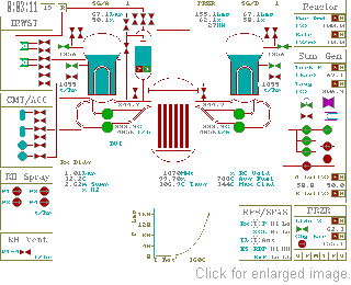
Figure 1
The simulator model developed for PWRs similar to AP600 will
be presented here. In the ARS the different reactor types are
simulated in a similar fashion with respect to man-machine interface
considering the specificity of each plant. The reactor primary
coolant has two steam generators and four coolant pumps (2x4
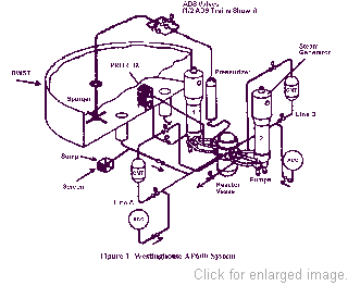
configuration). Figure 2 is a sketch showing
the primary components and the passive emergency core cooling
system. It will be simulated by a plant mimic, displayed as Figure 1.
On the mimic's right hand side, there are panels for the controls
of power demand, steam generators and pressurizer which are common
for all PWRs. Operation is defaulted to the automatic mode. If
at anytime the operator decides to take any of the control system
into manual operation, just clicks on the corresponding "M"
button and a window will show up. By entering a new set point,
activating the manual action and closing the window, the reactor
will then run on the manual mode. The Auto mode can be returned
by clicking at "A".
At the bottom of the mimic, status of the Reactor Protection
System (RPS) and Safety Feature Actuation System (SFAS) are displayed.
Reactor will be tripped automatically upon conditions exceeding
any of the RPS set points. The corresponding symbol will turn
into red. The reactor/turbine can also be tripped manually by
moving the mouse and clicking at the "T" (for trip)
button.
At left there are panels for the passive emergency core and
containment cooling systems. There is a In-Containment Refueling
Water Storage Tank (IRWST). It provides heat removal from the
Passive Residual Heat Removal (PRHR) system by natural circulation.
Three stages of Automatic Depressurization System (ADS) on top
of the pressurizer to relive steam into the IRWST during a small
break loss-of-coolant accident. The fourth stage ADS valves are
connected to the hot legs and relieve steam directly into the
containment atmosphere. Instead of an active HPI system, which
requires safety graded pumps and emergency AC power supply, there
is a passive system of Core Makeup Tanks (CMT) that fill into
the Direct Injection Line (DVI) by gravity. The Accumulators
(ACC) are filled with borated water with pressurized nitrogen.
Water in the IRWST can also be drained into the DVI when the
primary coolant is completed depressurized. For containment cooling,
the RB spray works on the outside surface of the containment
steel lining. And the vent is opened to draw air draft from the
lower part of the containment concrete wall openings.
Activation of the passive systems are indicated by the valve
color changes and digitally displayed flow rates. Operators usually
do not have to interfere other than verification and observation.

Figure 2
|


