PC-based Nuclear Power Plant Simulator
PCTran is PC-based reactor simulation software that conducts
nuclear power plant transient predictions at a speed faster than
real-time. The plant model presented in this version of PCTran
is of the ABWR designed for the Taiwan Power Company's Fourth
Nuclear Power Project Lungmen.
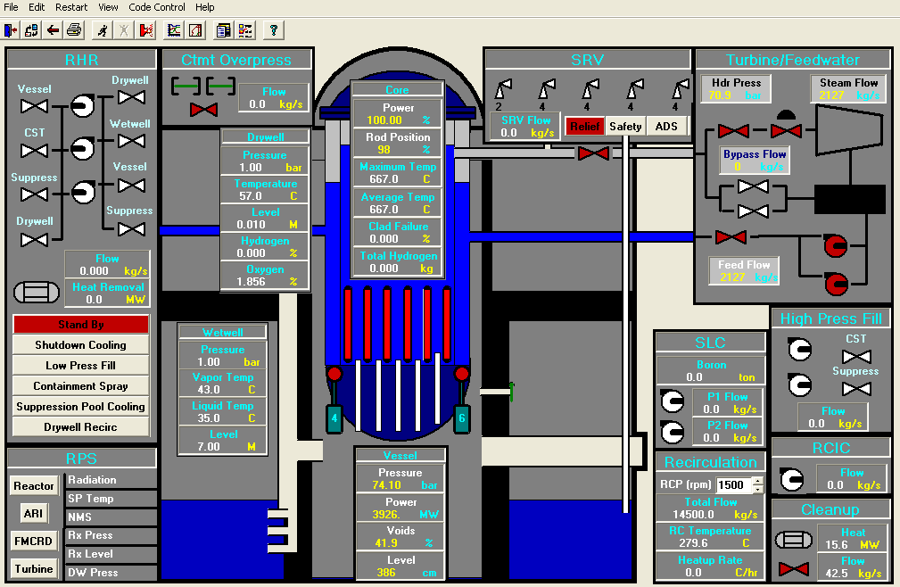
The main screen displays a mimic of the Nuclear Steam Supply
System with panels of controls for the most important equipment. Download the free demo.
PCTRAN for ABWR Verification
The plant model is the General Electric (GE) designed Advanced Boiling Water Reactor (ABWR) plant of 1300 MWe. The Standard ABWR Final Safety Analysis Report (SFAR) and Taiwan Power Company’s Fourth Nuclear Power Plant Lungmen (Dragon Gate) Project was used for PCTRAN-ABWR model input. The demo download package contains detailed benchmark results.
Ten Reactor Internal Pumps (RIP) are separated into two groups: four will be tripped on reactor trip; the remaining six (which are tied to a MG set) will be tripped on low reactor water level L2 or high dome pressure set point. During normal operation the operator can manually set the RPM to change the core flow. Load change can be controlled by combination of RIP’s master RPM demand and rod position control.
The upper and lower drywell is modeled in the containment model. The suppression pool (wetwell) surrounds the drywell. Horizontal vents connect the two compartments. There are vacuum breakers to balance the pressures of the two compartments after a major blowdown.
Eighteen Safety/relief valves (SRVs) are modeled in either the relief mode or the safety mode. Users have control to switch from one to another. In the relief mode there are six opening and closing bands, and in the safety mode there are five bands. For Automatic Depressurization System (ADS) actuation, eight valves will be opened at reactor water level below L1 (15.3 cm Top of Active Fuel or TAF) and high drywell pressure signal (1.25 bar) with 29 seconds delay or L1 only with 480 seconds delay. The following RPS signals have been modeled:
- Reactor low water level L3 = 3.75 meters TAF (Top of Active Fuel)
- High reactor dome pressure = 78.7 bar
- MSIV closure
- High flux (125% of nominal or flux-flow map)
For a malfunction of anticipated transient without scram (ATWS), reactor trip will be bypassed for the above conditions. Then four of the RIPs will be tripped and the Alternate Rod Insertion (ARI) will be started with an insertion time of 25 seconds. The ARI button in the RPS panel will be lit automatically upon its initiation. In the event of ARI is also lost for the malfunction, the operator can choose (manual action) either to drive in the rods by Fine Motion Control Rod Drive (FMCRD) run-in in135 seconds or start the Standby Liquid Control (SLC) boron injection pumps. The remaining six RIPs will be tripped on L2 condition. It further reduces the reactor power for ATWS mitigation.
The Reactor Coolant Isolation Cooling (RCIC) system will be initiated at (2.43m TAF) or high drywell pressure with 29 seconds time delay. The flow is a constant 38.8 Kg/sec for the reactor pressure between 10.55 to 82.75 bars.
Two of the 3 RHR pumps in LPFL model will be initiated automatically on L1 or high drywell pressure. Suction will be from the suppression pool and discharge into the reactor vessel. The pump’s flow rate is provided by a head curve provided in the FSAR. The discharge valve to the reactor vessel will be opened at 35.2 bar to allow water entering the vessel. The pumps will be automatically shut if the reactor water level recovers above L8 (4.91m). During an extreme emergency or exercise when the suppression pool cannot provide water, operator can manually line up suction from the plant fire water system.
The same RHR pumps are used for normal shutdown cooling, containment spray and wetwell cooling. They are initiated manually either by pressing the mode switch in the RHR panel or by controlling the individual pumps and valves for a given mode. For shutdown cooling, water is drawn from the reactor vessel and cooled by the RHR heat exchangers before returning back to the vessel. This can only be conducted when the reactor pressure is below 9.2 bars. For containment spray or suppression pool cooling mode, water is drawn from the suppression pool and running through the RHR heat exchangers. The operator for spray mode operation opens separates spray discharge valves into the drywell and wetwell air space. For the suppression pool-cooling mode, the water is returned into the suppression pool
Two HPFL pumps will be initiated automatically on L1.5 = 0.987m TAF with 36 seconds time delay. The pump’s flow rate is provided by the FSAR. The pumps will be stopped on reactor level above L8.
Two rupture disks have been modeled for over-pressure protection. They will be broken upon the suppression pool air space pressure over 7 bars absolute.
II.A PCTRAN Windows Operations
The Windows version is a state-of-the-art product taking full advantage of 32-bit PC technology. The source code is completely re-written using Microsoft Visual Basic 6. Operation follows strictly the Microsoft Windows XP environment. Data input/output are in Access database format. Reports and data can be transferred conveniently through Office Suite over a network. Execution is default to real-time speed. It could be accelerated to 2, 4, and 8 or up to16 times faster. Selection of equipment malfunctions and accident types are from a drop-down menu. It includes all possible disturbances to a plant:
- Normal operation control – start-up, shutdown, power ramp
- Loss‑of‑coolant‑accident (LOCA) or steam line break
- Loss of flow, single or two‑phase natural circulation
- Turbine trip with or with bypass, station blackout
- Steam generator tube rupture (PWR)
- Feedwater transients (pipe break, loss of feed or loss of heating)
- Anticipated transient without scram (ATWS)
- Containment failure (failed isolation or containment breach)
- Loss of AC power (loss of offsite grid and loss of diesel emergency power)
- Any combination of above
Online “Help” is provided that assists comprehensive user’s manual for easy instruction.
II.B Verification Analysis and Applications
A main steam line break inside containment case was analyzed using PCTRAN/ABWR for benchmark against the plant’s Preliminary Safety Analysis Report. The reactor dome pressure, break flow and ADS flow, High-pressure Core Flooder, Reactor Coolant Isolation Cooking, and Low-pressure Flooder flows are compared in the following figures. On the Left are PCTRAN calculated and right are PSAR images. They are generally in good agreement. PCTRAN/ABWR was used for Software Safety Analysis (SSA) of Lungmen’s digital I&C systems by the Institute of Nuclear Energy Research of Taiwan.
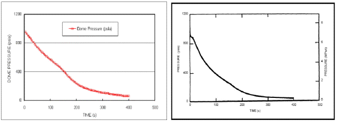
Fig. 2a ABWR MSLB - Reactor dome pressure
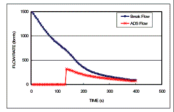 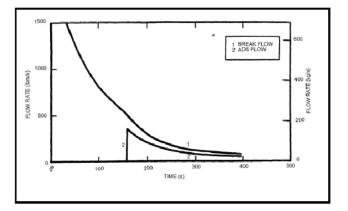
Fig. 2b ABWR MSLB Break and ADS Flows
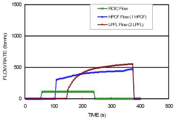 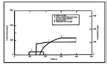
Fig. 2c ABWR MSLB HPCF, LPFL, RCIC and Feedwater Flows
|